Direct-On-Line (DOL) motor starting is a method that applies full voltage to an induction motor and suited for fixed-speed motor applications.
The typical DOL motor starter can comprise of circuit breakers, contactors, and overload relays, with components selected based on the application. These are usually encased in an enclosure to protect against dust and water ingress.
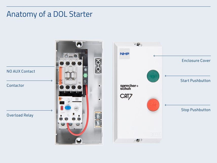
Where a contactor and overload are provided in an enclosure, this is commonly referred to as a DOL starter.
The contactor switches power to either START and STOP the induction motor. In the DOL setup, is wired along with operator control devices such as start, stop, reset, and emergency stop buttons, allowing for manual control of motor functions.
When a control voltage is applied to the contactor coil, its main power poles close, delivering full voltage to the induction motor, the motor as a result draws a high inrush current value (Locked Rotor Current), which is typical of full-voltage starting.
While some applications are well-suited to this type of starting, others may require a gradual voltage increase to reduce the inrush current. For these cases, a reduced voltage starter, such as a Star-Delta starter or Soft starter, is preferable for fixed-speed applications.
DOL motor starters make use of overload relays, to protect the motor from overcurrent conditions. When a motor starts, it generates torque (Locked Rotor Torque) from a standstill and gradually increases its speed. Initially, it draws a high inrush current value with application of full-voltage, which decreases as the motor speeds up, becoming noticeable around 85% of its maximum speed to its normal running current (Full Load Current).
The DOL starter can be wired for single, two, and three-phase configurations, offering versatility in various applications.
Contactors
As mentioned, a contactor is a power switching device that uses electromagnetic principles to function as a switch and control flow of electricity in a circuit to the load.
The internal design features a copper wire coil, formed around a magnetic iron core. When a control voltage (typically 240V AC or 415V AC) is applied to the coil, current flows through the wire, generating an electromagnetic field that attracts the metallic armature at the bottom of the moving contacts. This pulls the contacts down, forming a circuit with the connected load and powering the motor. When the control voltage is removed from the contactor coil, the electromagnetic field around the core collapses which releases the movable contacts with the armature back into its original de-energised state, removing the power from the motor.

Contactors are selected based on factors such as the kW rating of the motor to switch, coil voltage required, and auxiliary contacts including their configurations. Contactors provide a safe, convenient, cost-effective way of controlling motors.
Motor Overload Relays
The DOL motor starter incorporates the use of an overload relay which protects the motor from overcurrent conditions. This overload is usually directly connected to the contactor.
Excessive current can damage the motor insulation windings hence guarding against overcurrent is essential to avoid motor thermal failure and to extend its lifespan. When an overcurrent condition is detected based on the trip level setting on the overload, the overload auxiliary cuts off the control voltage signal to the contactor coil, de-energising the motor. An overload auxiliary can also signal an overload condition as part of feedback to a control system, or a light for visual indication.
There are two main types of overload relays:
Thermal overload protects motors from overcurrent by detecting excessive heat, as Overcurrent causes internal bimetallic strips to heat and bend, thus opening an auxiliary contact, tripping the circuit to indicate an overload. Although accurate and easy to use, thermal overloads dissipate more heat compared to electronic overload types.
Electronic overloads measure motor current via Current Transformers (CT’s) in conjunction with electronics (microprocessor) to provide accurate protection. As a result, electronic overloads provide accurate current settings, don’t waste energy generating heat, provide improved protection for different start and operating conditions and extensive protective, monitoring and control functions.
Some advantages of electronic overloads compared to thermal types include:
- Wider current adjustment range which means that one model can cover the equivalent current range of several thermal overloads e.g: One model replaces several thermal units
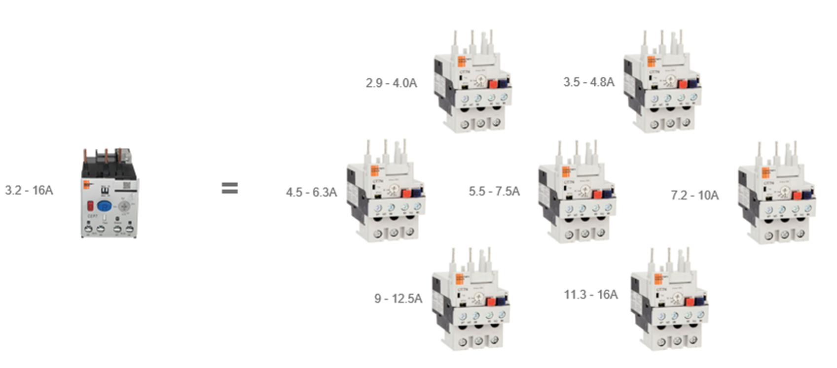
- Broader selection of trip classes
- Lower heat dissipation in comparison to thermal types
- Advanced models can support connection to protection modules like ground fault and motor jam protection, as well as status indication and remote overload resetting
Enclosure
An enclosure houses the electrical components of a DOL starter assembly, providing electrical safety for users, and protection against water and dust ingress to prevent component damage.
Different operator control devices, such as 22.5mm mount pushbuttons, pilot lights, selector switches and emergency stop buttons, maybe installed on the front face of the enclosure, providing basic control for starting and stopping the motor.
Knock-outs on the DOL enclosure allow for the convenient connection and management of your line and load side power cables.
Applications
Application examples of where DOL starters are used include:
- Exhaust fans and other Extraction systems
- Water pumps
- Compressors
- Industrial machines
- Commercial or Industrial based shutters
DOL’s provide a cost-effective, reliable solution for full-voltage motor starting, being ideal for applications that just need the motor to be turned ON and OFF without any requirement for gradual ramping or speed control. It has a simple design and provides the user with straightforward control for full-voltage motor starting.
Australia 1300 647 647 nhpsales@nhp.com.au